I have a moment to get the final post of this series finished (see my author page for parts 1-5). We went through the basic process of creating Windows Failover Clusters and adding SQL or other Generic Services to a Windows Failover Cluster. Everything that we did in the series so far was done in a lab environment as it was being written, and all of the screenshots have been from those exercises.
This final installment will be no different. Everything presented in this installment is out of the lab and has been built just as it is described. The Windows Failover Cluster is useful for protecting more dynamic forms of data, like SQL or email applications, but there is another type of cluster available in Windows which is more suitable for static forms of data like web services. That is the Network Load Balancing (NLB) cluster. The Failover Cluster will allow the completion of unfinished transactions if a node fails and a different node takes over. NLB does not behave this way. NLB is intended to distribute the load across multiple servers. One thing you will notice about the NLB setup as you run through this blog is that there is no requirement for shared storage. Therefore, the NLB cluster nodes need to be set up the same way, and the setup should remain static. If there was changing data housed on the nodes there would be no fault tolerance since there is no shared storage to handle fail over.
People cluster web front ends in different ways, and many people use dedicated hardware devices such as Kemp's LoadMaster, F5's Big-IP, or Cisco's CSS/ACE devices. A network engineer should determine the suitability of the load balancing methods of each device as it pertains to the application/web service you are working with, and I can't claim to be an expert in this area.
This blog will outline how to install the Microsoft Network Load Balancing feature in Windows Server 2012. The machine names for the nodes in this cluster will be NLBNODE1 and NLBNODE2, with a Network Load Balancing name of NLBCL.
The prospective NLB nodes must be configured as follows:

  • All nodes must be on the same subnet
  • All network adapters must use the same mode, multicast or unicast
  • If using unicast network adapters must support changes to their MAC addresses
  • Network adapters must be configured to use TCP/IP exclusively. No other protocols can be added.
  • IP addresses assigned to the network adapters must be static. DHCP is not supported.
Step Description
A - Roles and Features Open Server Manager on NLBNODE1 and scroll down to the bottom of the page. Click on the Tasks button and select Add Roles and Features as shown in the image on the left.
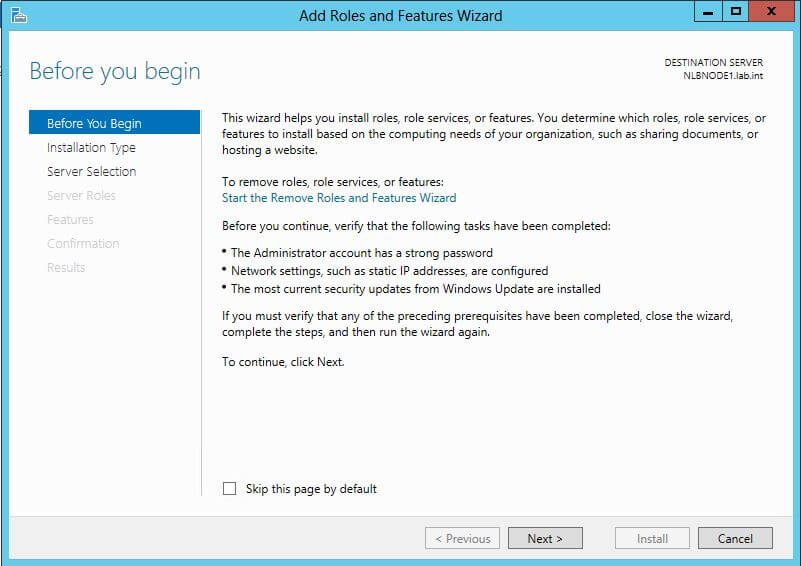
B - Before You Begin Next, click Next at the Before You Begin screen.
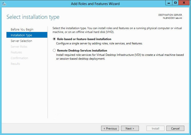
C - Installation Type in the Select Installation Type screen select the Role-based or feature based installation radio button and click Next.
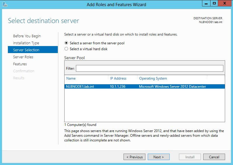
D - Server Selection in the Select Destination Server screen ensure that the Select a Server From the Server Pool radio button is selected and that the local server name is highlighted in the Server Pool window, and click Next.
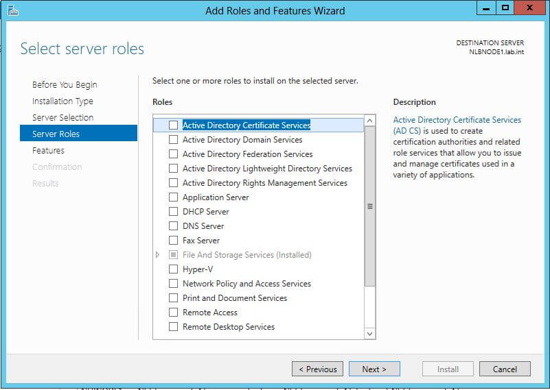
E - Server Roles In the Select Server Roles screen click Next.
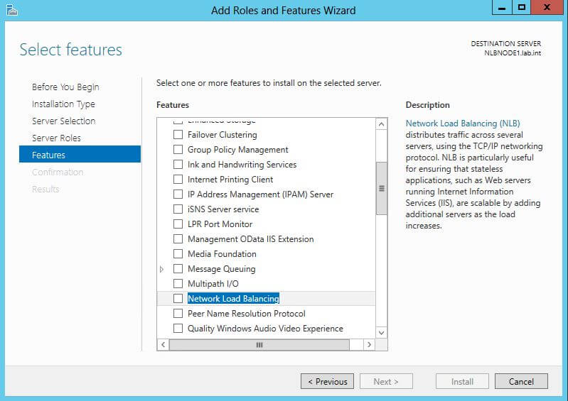
F - Features In the Select Features screen select the Network Load Balancing item. A subsequent screen will immediately appear to show other features that will be automatically added.
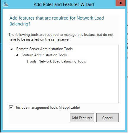
G - Add Features Click the Add Features button in the Add Features that are Required for Network Load Balancing dialog. You will be returned back to the Select Features screen and the Network Load Balancing item will be selected. Click Next to continue the feature installation.
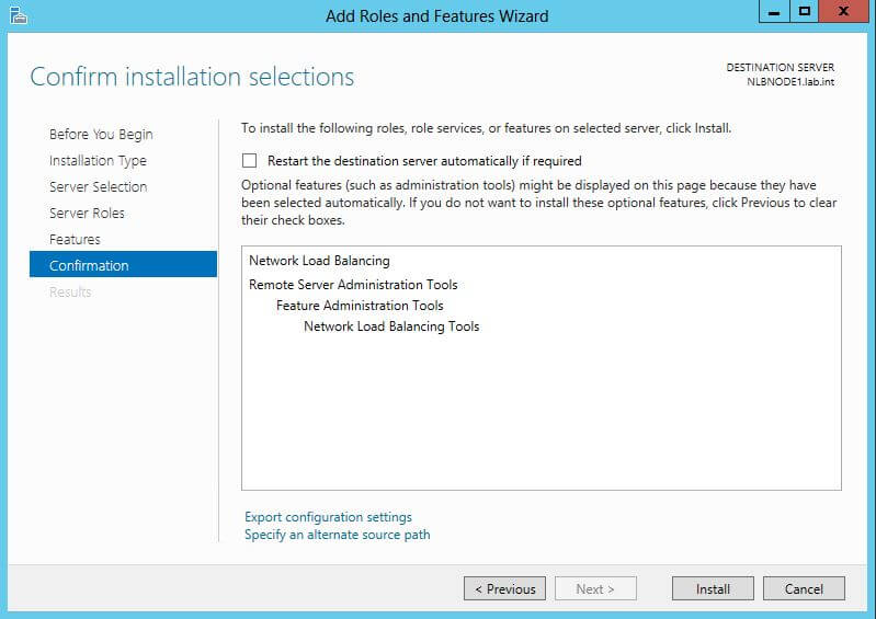
H - Select Features In the Confirm Installation Selections screen click Install.
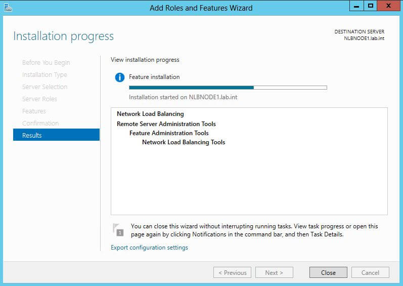
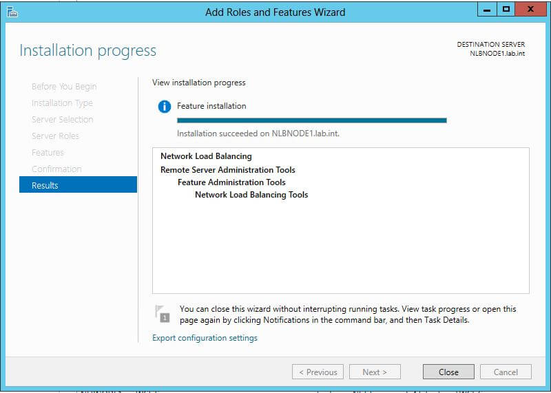
J - Installation Progress A progress bar in the installation Progress screen will indicate that the status of the NLB feature installation.
K - Installation Succeeded When the progress bar in the installation Progress screen indicates that the feature installation is complete click the Close button.
Perform the same steps as those above to install the Network Load Balancing feature on the other node (in this lab NLBNODE2) that will be a part of your NLB cluster.
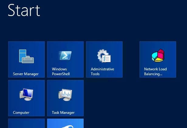
LA - Start Menu NLB Select the Network Load Balancing icon on the Start page of NLBNODE1.
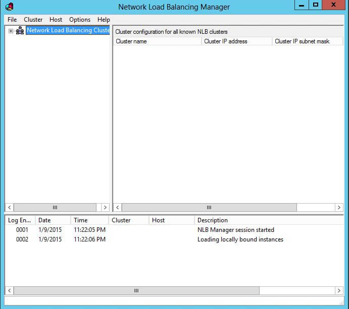
LB - NLB Manager A blank Network Load Balancing Manager console appears.
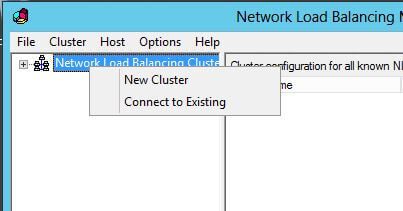
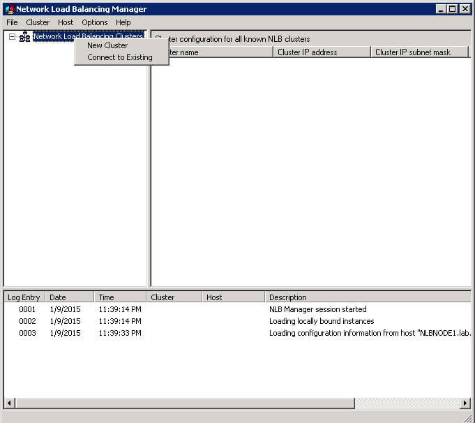
LC - New Cluster Right click the Network Load Balancing Cluster node as shown and select New Cluster from the context menu to start the creation of the NLB cluster.
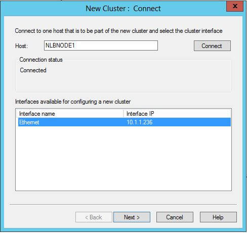
LD - First Node New Cluster Connect Enter NLBNODE1 in the Host: field of the New Cluster: Connect dialog. The machine I was configuring only had one network adapter installed, so only one appears in the interfaces section. If there are multiple NICs, choose the one that will be used for the NLB cluster. Click Next to continue with NLB cluster setup.
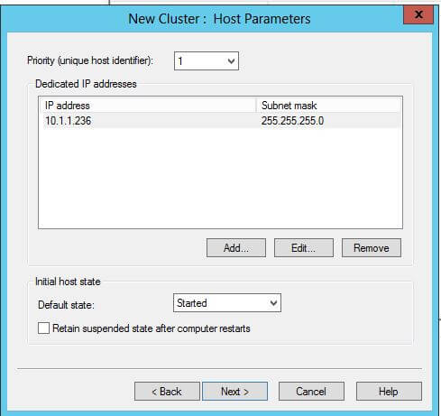
LE - Host Parameters Click Next at the New Cluster: Host Parameters dialog.The initial host state options can be configured based on the applications that the hosts in the NLB cluster will be running. If the app starts after a rebooted node joins the NLB cluster and you want to manually start the NLB cluster node or if you are using SCOM to manage your NLB cluster and Operations Manager will start the cluster node for you it may be desirable to configure the Default State to be Stopped. Leaving it at Started will allow the cluster node to start automatically after any reboot, but be aware that if the services being load balanced are started after the node has joined the NLB cluster there could be a small window in which a user might receive an error when trying to access the application through a newly booted node.When you stop a node's NLB clustering using the NLB command line the NLB node is placed in a suspended state. The other setting, Retain suspended state after computer restarts maintains any suspended state when a node is rebooted, and manual intervention will be required to rejoin the node to the NLB cluster. In this exercise the Default State will remain at the default value of Started and the Retain suspended state after computer restarts will remain unchecked.
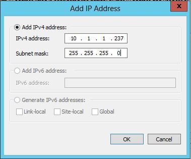
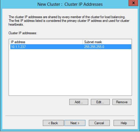
LF - Add IP Address for Cluster In the Add IP Address dialog provide the IP address that will be used to refer to the NLB cluster and the subnet mask. Clients connecting to this address will be directed to one of the nodes in the NLB cluster. In this setup the nodes are 10.1.1.235 and 10.1.1.236, and the cluster's IP is 10.1.1.237. The idea is not much different than the IP configuration we have already seen in the configurations covered earlier in this series. Click OK to continue.
LG - New Cluster IP Address In the New Cluster: Cluster IP Address dialog click Next to accept the IP address you entered.
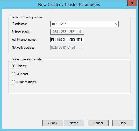
LH - New Cluster IP Config(Full) In the New Cluster: Cluster Parameters screen verify that the cluster's IP Address is shown and enter the FQDN name that you wish to give to the cluster. the other option you have here is the Cluster Operation Mode. there are three available options: Unicast, Multicast, and IGMP Multicast. Unicast replaces all of the MAC addresses for the clustered network adapters on all nodes with a single, matching MAC address. This means that the nodes of the cluster will be unable to communicate with one another. Also, if the network adapters in the cluster are connected to a switch all inbound packets are transmitted on all switch ports, which can cause switch flooding. If you need to allow the NLB cluster nodes to communicate with one another then you have two options. You can install a second network adapter in each node and not configure it for use by the NLB cluster or you can use one of the multicast options.The multicast options allow each network adapter in the cluster to retain it's original MAC address, therefore the nodes will be able to communicate with one another. The adapters are also assigned a multicast address. The network equipment throughout the solution must be able to handle multicast.The IGMP Multicast option can be used to minimize the possibility of switch port flooding by ensuring that traffic intended for the NLB cluster is limited to only switch ports to which your NLB cluster nodes are connected.
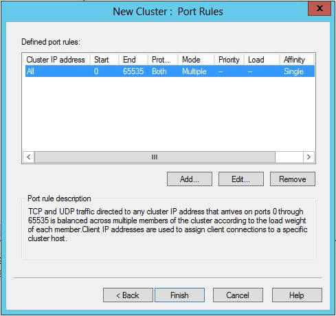
LI - Port Rules Click Finish at the New Cluster: Port Rules dialog to complete the NLB cluster configuration.
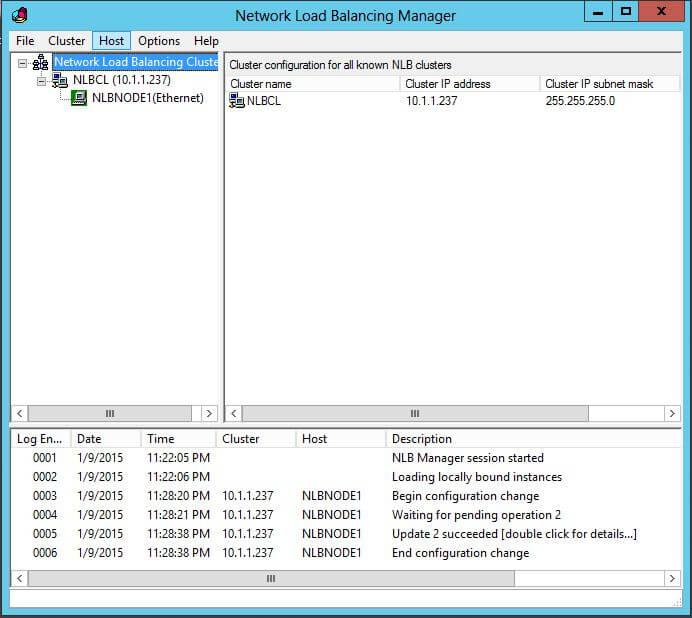
LJ - Cluster Created Now in the Cluster Created dialog we see the NLBCL cluster and the NLBNODE1 node is added to it. Now we will add the NLBNODE2 system to the Load Balancing cluster and it is here that you will be able to see the effect of the cluster operation mode (Unicast or Multicast) which we selected a few steps earlier.If you were to try to add the second node from the Network Load Balancing Manager console that you currently have open you would find that you were unable to add the node. While you would be able to enter all the relevant information into the Connect to Existing wizard, the node might not be configured and might not show up in the console. This is because the nodes are being configured for Unicast and nodes in Unicast use the same MAC address, which can interfere with communications between the nodes. Therefore, I used a machine that was not part of the cluster to add the second node. The following steps are shown from that machine.
MA - Connect to Existing Install and open the Network Load Balancing Manager from a machine that is not part of the cluster. Right click on the Network Load Balancing Clusters node and select Connect to Existing from the context menu.
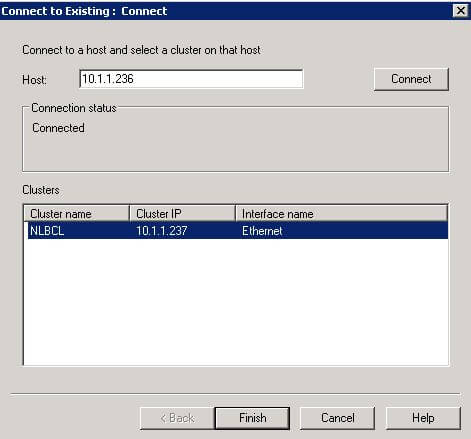
MB - Connect to the First NLB Cluster Node In the Connect to Existing: Connect screen enter the name or IP address of the node that is already a part of the cluster (in our case NLBNODE1) in the Host field. Click Connect. When the cluster name (in our case NLBCL) appears in the Clusters pane click the Finish button.
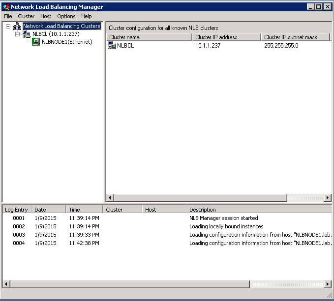
MC - The First Node by Itself Now you will see the Network Load Balancing Manager with the NLBCL cluster populated with the NLBNODE1 machine, just as it appeared three steps previously.
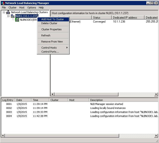
MD - Add Host To Cluster Now, right click on the cluster name (NLBCL) and select Add Host to Cluster from the context menu.
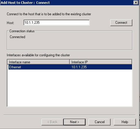
ME - Connected to the second node In the Add Host to Cluster: Connect enter the name or IP address of the second host (NLBNODE2) in the Host field. When the network connection is listed in the Interfaces available for configuring the cluster pane select it and click Next.(
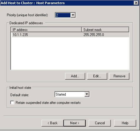
MF - Host Parameters Click Next at the Add Host to Cluster: Host Parameters screen. The parameters will be the same as they were when we configured the parameters while originally creating the cluster with NLBNODE1. The only difference is that the priority will be automatically set to 2 in order to keep it unique.
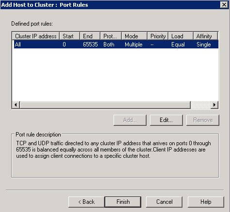
MG - Port Rules Click Finish at the Add Host to Cluster: Port Rules screen. We aren't changing anything here for our lab cluster.
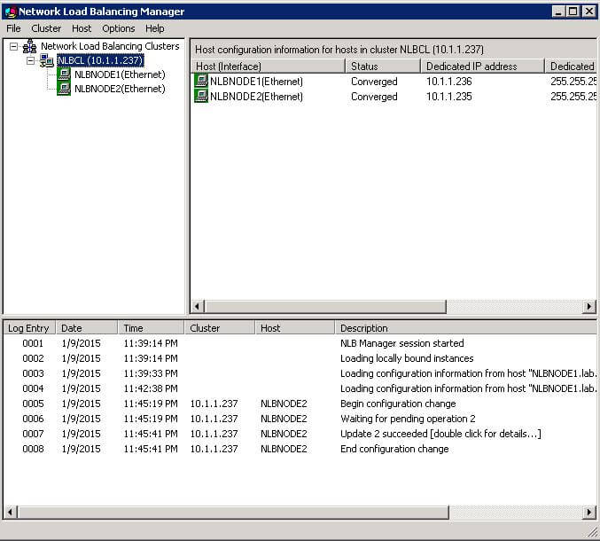
MH - Both Nodes Added Finally, we see the NLB cluster with two nodes added.
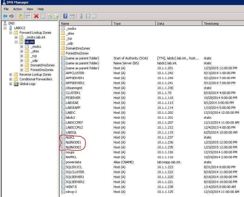
N - DNS HOST Entry In the DNS Manager screenshot here you can see the DNS entries created during previous exercises in this series. In the case of the NLB we have entries for the hosts but no DNS entry was created for the NLB cluster as was the case with the other clusters we created. In this case we need to manually create the DNS HOST entry for the NLB Cluster. This was already done here. You can see the entry for NLBCL with a value of static in the Timestamp column. Once the cluster's DNS entry is created it can be accessed through a browser by name.In order to do a rudimentary test of the NLB cluster function we will install IIS on each node and create a Virtual Application on each node. The name of the virtual app must be the same on each node.
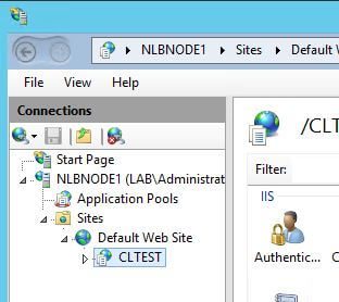
O - VirtualAppCLTEST The Virtual Application CLTEST was created on both nodes in the IIS Manager application, and a web page named webpage.html was created on each node which simply displays some text and the node from which it is being served. It is a simple HTML page with the corresponding node names in each.

Now we can begin testing. The URL https://nlbcl/cltest was entered in a browser and the page came up as expected, showing the name of the cluster node that is serving the content.
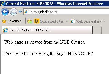
P2 - NODE2HTML
I closed the browser several times, but it just kept hitting the same cluster node, NLBNODE2. If you review the settings that we made while configuring the cluster there was a setting on the Port Rules screen named Affinity. It is set to Single by default, and we selected the default settings on the page.
Single Affinity directs subsequent requests from the same host to the same cluster node. This is the setting that must be used when applications need to maintain user state information, such as when your cluster nodes are hosting HTTPS traffic. If your application is stateless then you can use the Affinity setting of None. This will allow the cluster to randomly select the node that will serve the content.
Right click the cluster name in the NLB Manager console and select Cluster Properties from the context menu. In the cluster properties dialog select the Port Rules tab, select the rule that was created when you set up the cluster, and click Edit. Here you can select None from the Multiple Host frame of the Filtering section. Save your changes and try accessing the page multiple times as we did before. Now you should notice that you are directed randomly to different nodes.
That is the basic setup of a Microsoft NLB cluster. As I said at the beginning, NLB clusters are not used for applications that handle dynamic data like database transactions or email. The Failover Clusters that we looked at earlier are better suited to those types of applications. The NLB cluster is meant for web based content that is more static in nature.
I hope that this series has been helpful to someone out there. I wanted to try to collect information and present it in one place. I thought that might make it easier for people to start with some clustering exercises to see how the technology might work in their environments.
Until next time, happy trails to you all 🙂